 Statement Furniture
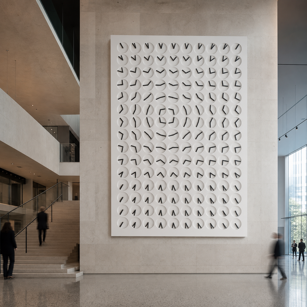
WorkInterval 96
TypeKinetic Dial Sculpture
Standard dimensions1200 W × 1800 H × 145 D mm · 96 dials · architectural arrays by study
CommissionFrom Rs. 1,600,000
Kinetic Dial Sculpture · AUTHË Kinetic Works
Commission
Interval 96
Commission from Rs. 1,600,000
Base sculpture · site engineering, delivery and installation quoted separately
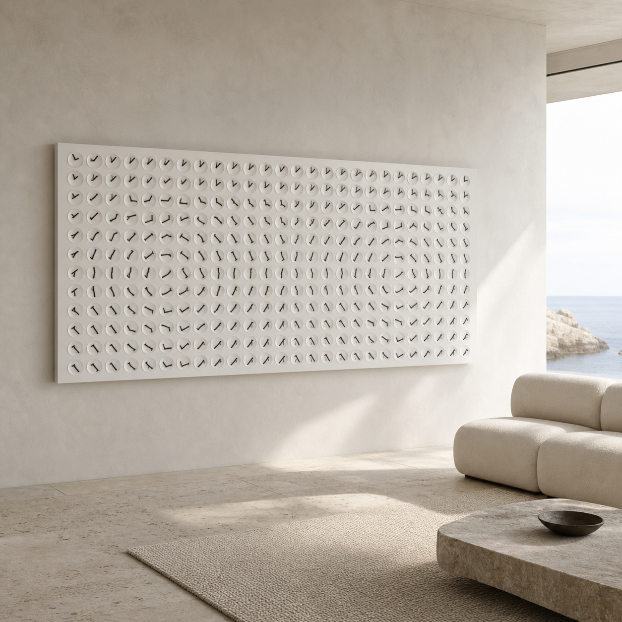
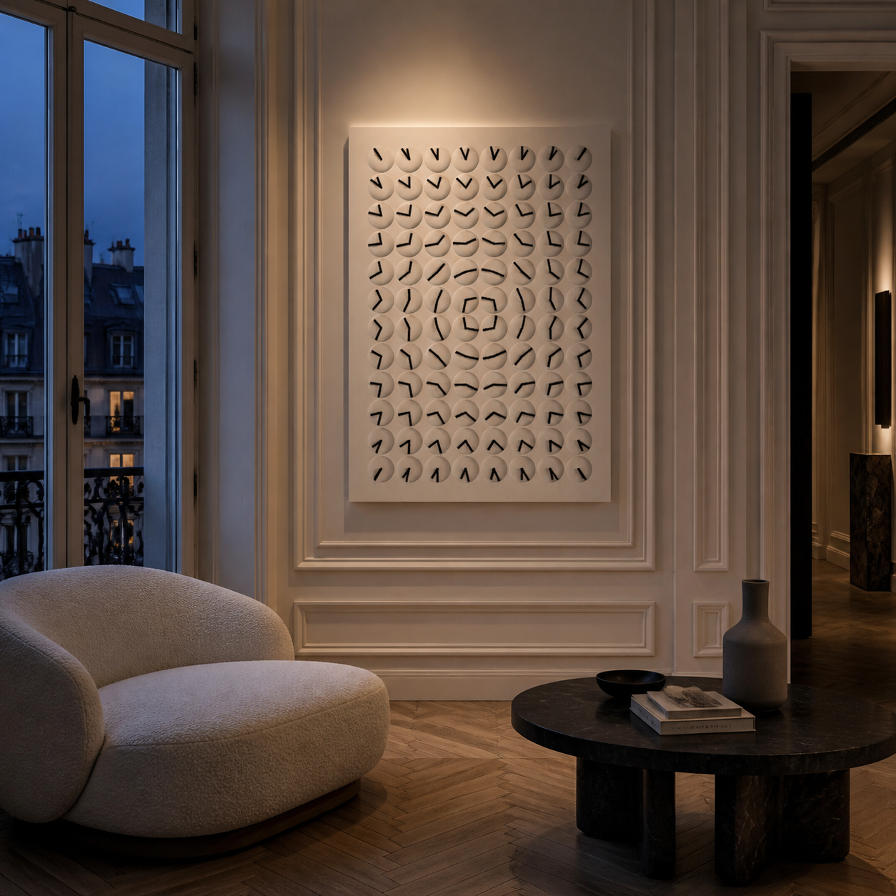
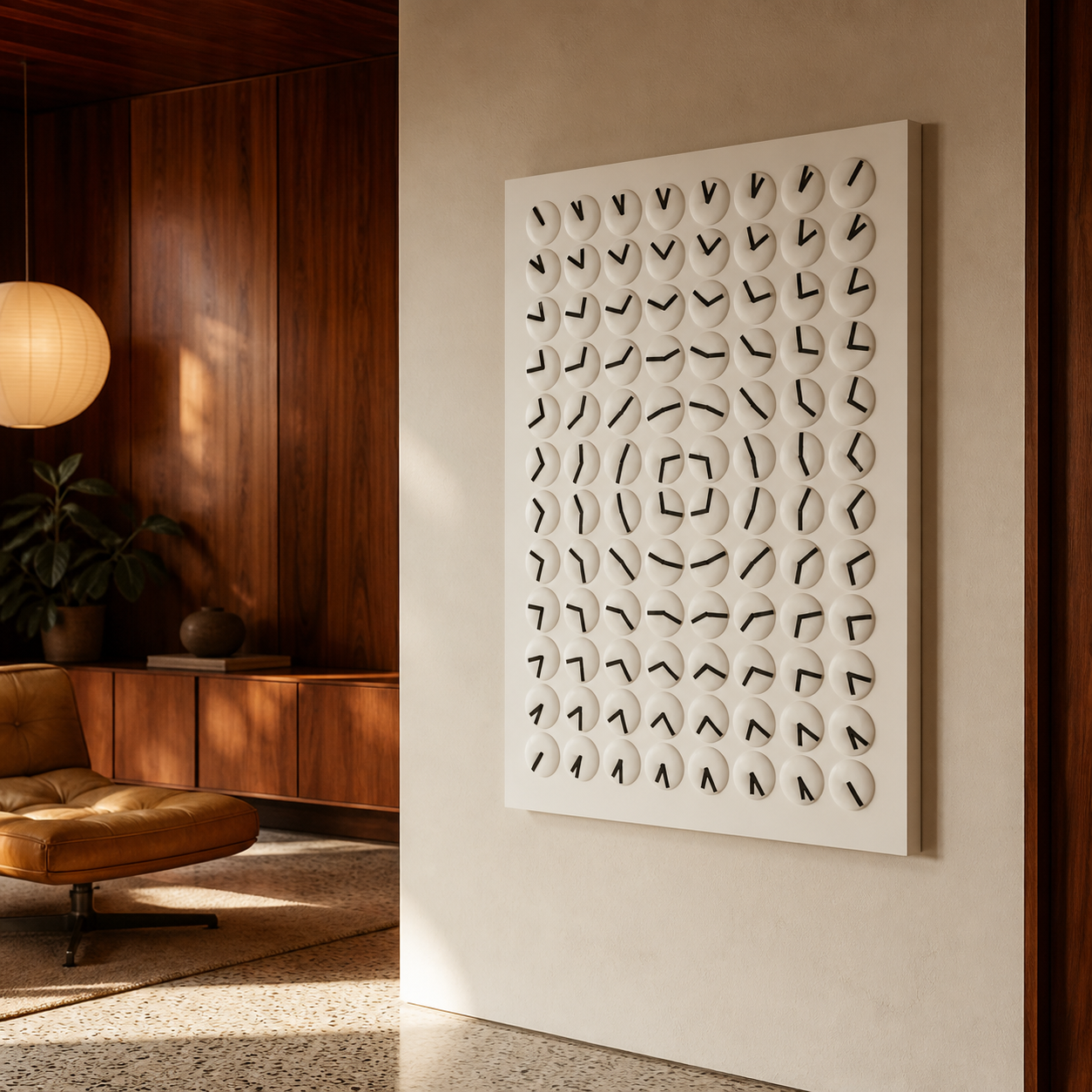
Interval 96 is a wall-mounted kinetic work composed of ninety-six independently driven dials. Each dial carries two black hands. Their rotations gather into lines, openings and slow fields before separating again.
The standard work is built as four serviceable drive cassettes behind a mineral-white face. Power and data connections are numbered, the wall rail is concealed, and individual motion modules can be removed without dismantling the complete work.
Movement
Studio-authored sequences move between ordered alignments and open compositions. Programme timing, quiet hours and building-control triggers are set during commissioning. The work can be configured for residential, hospitality, workplace and public interiors.
For architects and collectors
The listed studio configuration measures 1200 × 1800 mm. Wider fields and site-specific arrays are developed from wall elevations, viewing distance, access, power and control requirements. Final fabrication begins after approval of drawings, finishes and movement studies.
Commission configurator
Configure a commission
Step 1 / 4
Delivery
Custom crating, insured freight and installation quoted to destination
Lead time
16–22 weeks after design approval and deposit
Documentation
Signed record, approved drawings, operating guide and maintenance plan
Studio price
Commission development, sculpture modules, selected studio finish, control enclosure, studio testing and signed handover dossier.
Project price
Site-specific structural engineering, custom crates, insured freight, taxes and duties, rigging, installation and final calibration.
Technical dossier
Dimensions
1200 W × 1800 H × 145 D mm · 96 dials · architectural arrays by study
Materials
Mineral-composite face, powder-coated aluminium chassis, black aluminium hands, electronic and motion-control components
Motion
Ninety-six independently driven dual-hand modules; studio-authored sequences, quiet holds and site-timed programmes
Power
100–240 V AC isolated supply; concealed low-voltage distribution; local, scheduled or building-control trigger
Edition
Numbered launch edition of 24 standard works; architectural configurations commissioned separately
Installation
Wall-mounted on a levelled structural rail; substrate, service clearance, power and controls confirmed during site review
Series
Kinetic Dial Sculpture
Made in
Designed, engineered and built in India
Documentation
Studio-signed project record, approved drawing set, configuration schedule, operating guide and maintenance plan
Modular construction
Four 600 × 900 mm serviceable drive cassettes form the standard work.
Numbered quick-connect power and data allow modules to be bench-tested and replaced individually.
Numbered quick-connect power and data allow modules to be bench-tested and replaced individually.
Packing and assembly
Numbered cassettes, face modules and concealed rail ship in reusable foam-lined crates.
Final crate sizes and installation sequence follow the approved access survey and packing drawing.
Final crate sizes and installation sequence follow the approved access survey and packing drawing.
Installation and ownership
Configuration and site review
The selected scale is the starting configuration. Final dimensions, structure, clearances, finish, movement and controls are confirmed against site drawings before fabrication.
Power and controls
100–240 V AC isolated supply; concealed low-voltage distribution; local, scheduled or building-control trigger Power location, switching, control integration and cable routes are shown in the approved project drawings.
Installation
Wall-mounted on a levelled structural rail; substrate, service clearance, power and controls confirmed during site review Structural capacity and local compliance remain subject to review by the project team.
Shipping and field assembly
Numbered cassettes, face modules and concealed rail ship in reusable foam-lined crates. Final crate sizes and installation sequence follow the approved access survey and packing drawing. Freight is quoted after crate size, weight, destination, insurance and access are confirmed.
Service and replacement parts
Numbered modules and reversible connections are planned so drives, controls, lighting and optical components can be inspected or replaced individually. The final handover includes an operating guide and maintenance plan.
Technical drawing · concept issue 01
Interval 96 · technical outline
Standard commission envelope shown. Final dimensions, loads, fixings, power, service clearances, module breaks and crate sizes are issued after site review.

Specifications
Dimensions
1200 W × 1800 H × 145 D mm · 96 dials · architectural arrays by study
Materials
Mineral-composite face, powder-coated aluminium chassis, black aluminium hands, electronic and motion-control components
Movement
Ninety-six independently driven dual-hand modules; studio-authored sequences, quiet holds and site-timed programmes
Power
100–240 V AC isolated supply; concealed low-voltage distribution; local, scheduled or building-control trigger
Installation
Wall-mounted on a levelled structural rail; substrate, service clearance, power and controls confirmed during site review
Edition
Numbered launch edition of 24 standard works; architectural configurations commissioned separately
Lead time
16–22 weeks after design approval and deposit
Modular construction
Four 600 × 900 mm serviceable drive cassettes form the standard work.
Numbered quick-connect power and data allow modules to be bench-tested and replaced individually.
Numbered quick-connect power and data allow modules to be bench-tested and replaced individually.
Packing and delivery
Numbered cassettes, face modules and concealed rail ship in reusable foam-lined crates.
Final crate sizes and installation sequence follow the approved access survey and packing drawing.
Final crate sizes and installation sequence follow the approved access survey and packing drawing.
Made in
Designed, engineered and built in India
Drawing
Related works
Statement Furniture
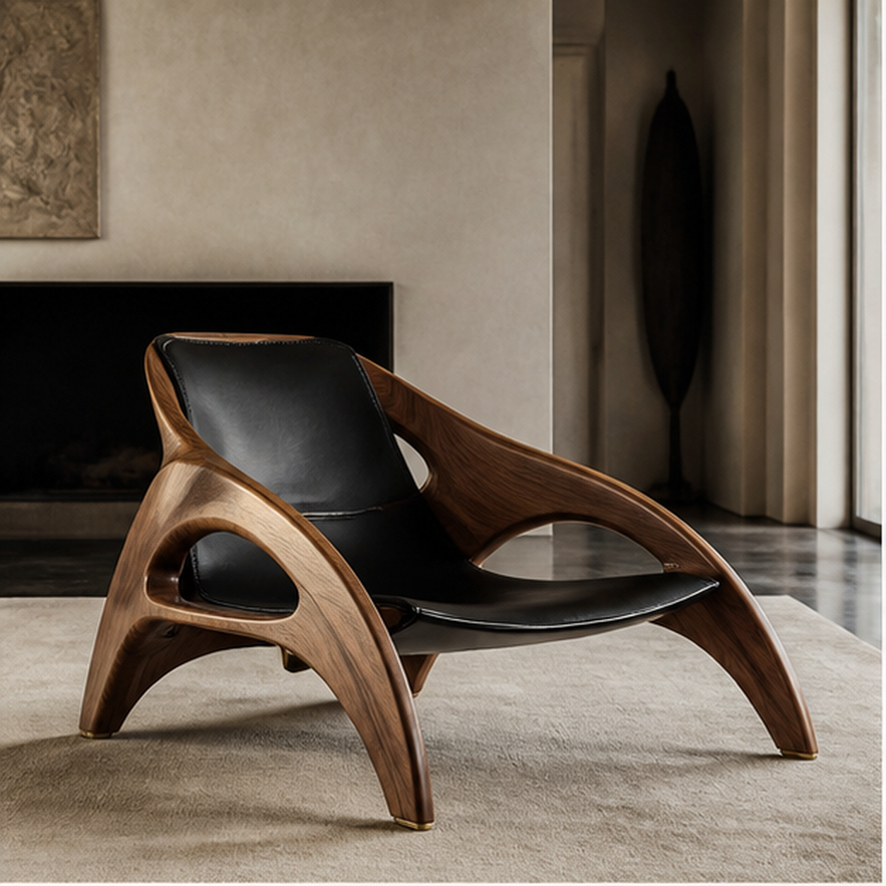 Statement Furniture
Arc Lounge
From Rs. 480,000
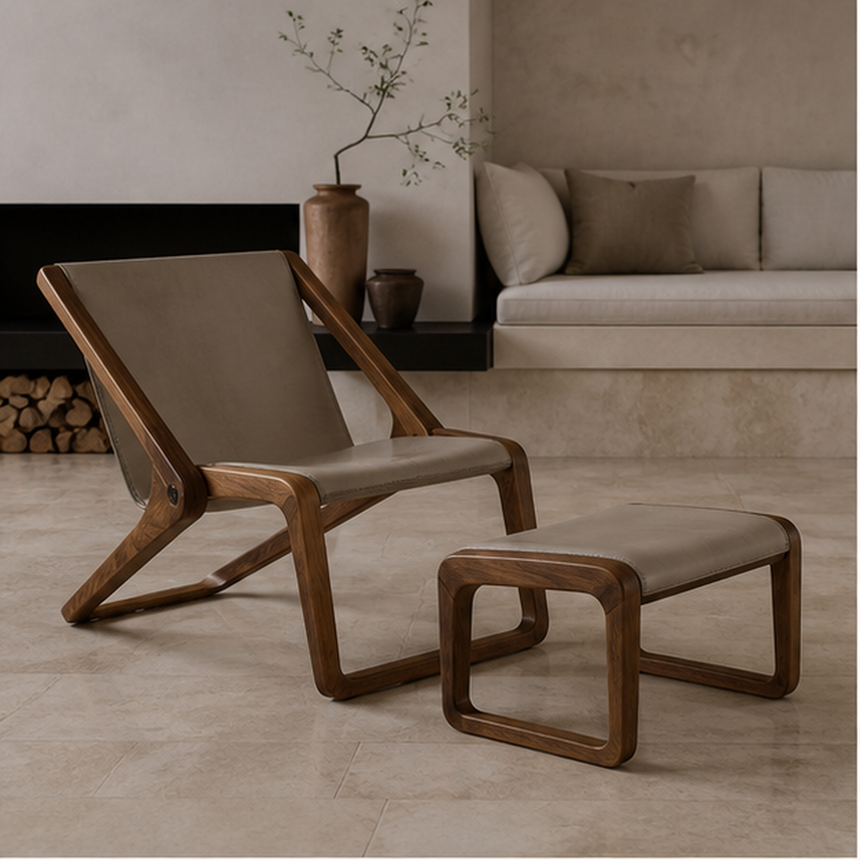 Statement Furniture
Fold Lounge
From Rs. 380,000
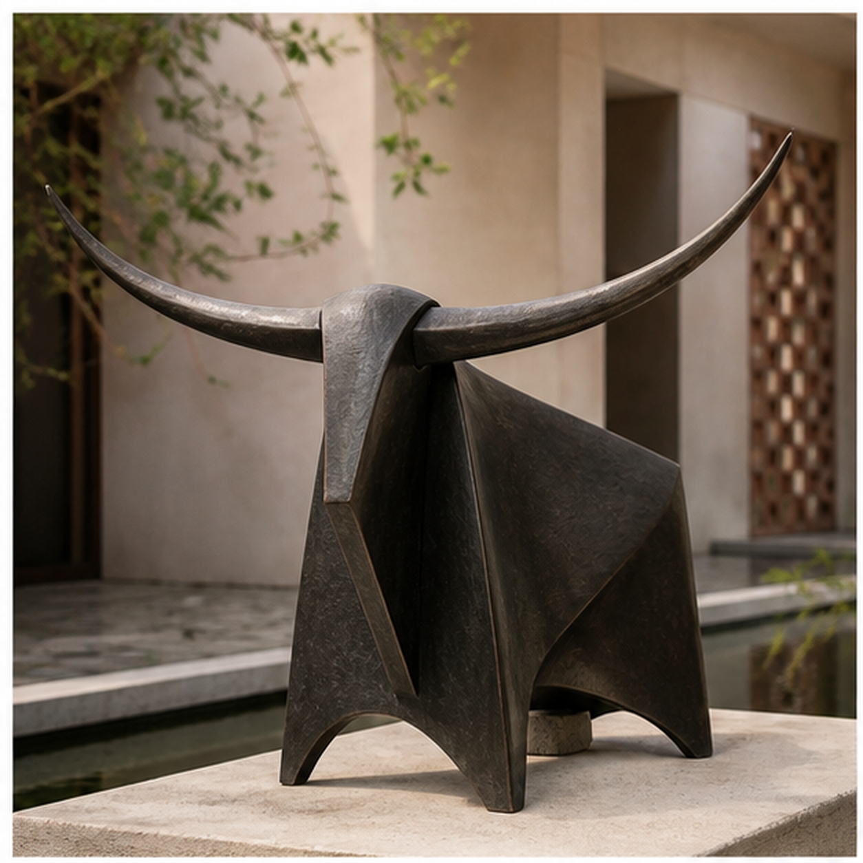 Sculptural Object